 News
News
First experimental tests on the prototype of a capacitive…
Methodology: In order to design a novel CLS, a first look is given at the conventional cylindrical probe. This is indeed similar to a capacitor with cylindrical armatures, and its capacitance is given by the equation:
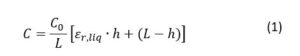
where C0 is the dry capacitance, h is the height of the liquid, L is the length of the probe and ε is the dielectric constant of the liquid. From here, the capacitance per unit of length is: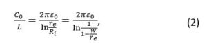
where ε0 is the vacuum/air permittivity, re is the inner radius of the external electrode, Ri is the outer radius of the internal electrode and w is the gap between the electrodes.
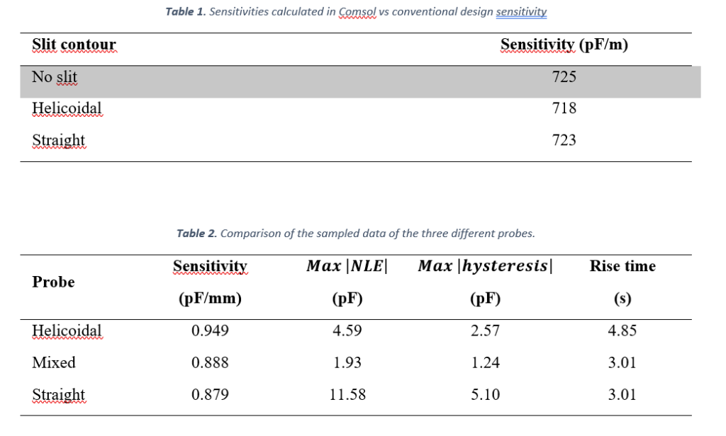
It is clear that a way to improve the sensitivity of the sensor is narrowing the gap w. Thus, as explained in [2], narrowing the gap between the two electrodes can make capillarity rise and the communicating vessels phenomenon to happen. The capillarity effect can be numerically modelled and addressed by engraving slits into at least one of the concentric probes so that no column above the bath level can build up in the channel. Two kinds of contour have been considered for the slits: helicoidal and straight. Both were carefully modelled and studied in COMSOL Multiphysics® to calculate the physical characteristics, in particular their sensitivities (Table 1). A third probe, with helicoidal slit on the external probe and the internal probe with no slits was tested too. This will be referred as “mixed”.
The conditioning circuit described in [1] is used for the readout of the prototypes of the probes. It consists in an Integrated Circuit by Texas Instruments that can be interfaced with an Arduino Uno. The sampled data is then processed in MATLAB.
To simulate the oil level change, a stepper motor was used to move the probes with high precision inside and outside of a cylinder full of lubricant oil by Viskoil.
For each sensor, sensitivity, hysteresis, rise time, and root mean square non-linearity error (RMSE) have been studied and evaluated to carry out a comparison.
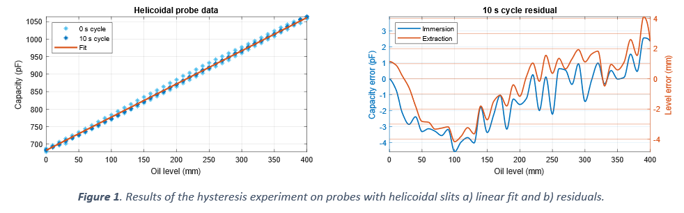
Hysteresis experiments were done with three immersion and extraction cycles of the probes with increasing pause times between the moving and the sampling phase. The experiments were performed over a full run of 400 mm in 10 mm steps. For each step, after a delay time (if added), 100 samples were taken in a time interval of about 2 s. The mean absolute hysteresis is calculated as the mean of the differences between the immersion and extraction measures. The sensitivity is calculated by fitting the 10 s cycle data with a first-grade polynomial function.
The rise time experiments were performed by measuring the sensor’s output capacitance for a minimum of 20 s, after rapidly dipping or extracting the probe into/from the oil. The time constant 𝜏63 was calculated as 63 % of the time from the moment the sensor stopped to the moment its output capacitance reached its settled value. Settling time was then assumed to be 𝑡𝑟=5∙𝜏63.
The same sampled data were also used to calculate the sensitivity of the sensor and the RMSE, both for the immersion and for the extraction movements.
Results: Table 2 and Figure 1 show some of the obtained results. According to the hysteresis experiment, the sensor with mixed electrodes showed overall the least residual non-linearity. With respect to the rise time evaluation experiments, the main issues arose with the helicoidal probe; in fact, in this case, we observed a very high time constant since i) the gap between the two electrodes is very narrow and this increases the time needed for the oil to rise and fall in the gap, and ii) the slits are narrow too, allowing a thin membrane of oil to form in them. In this case, the vertical slit electrodes performed best, even though the results are comparable to the mixed electrodes ones. Finally, a preliminary look was given at the dynamic performance of the sensors. The residual non-linearity RMSE is comparable for all three probes. Results for the immersion and extraction are similar too. However, when fitting the sampled data and calculating the sensitivity, a clear difference between the extraction and immersion characteristics arises, with the sensitivity for the immersion being lower than the extraction.
Conclusions: The probes have been prototyped and tested using an in-house developed PC-based mechatronic system and readout electronic. Concerning the sensitivity, the proposed sensor showed an improvement of more than three times with respect to other commercial CLSs. Furthermore, the issue of the second-order response in response to a step change in the oil level was overcome, with an improvement in the settling time too.
References:
[2] Adamo, F.; Attivissimo, F.; de Gioia, S.; Lotano, D.; Di Nisio, A. “A design strategy for performance improvement of capacitive sensors for in-flight oil-level monitoring aboard helicopters”, Measurement, 2023, 112476, ISSN 0263-2241, DOI: 10.1016/j.measurement.2023.112476.
[3] Adamo, F.; Attivissimo, F.; De Palma, L.; Lotano, D.; Di Nisio, A. “First experimental tests on the prototype of a capacitive oil level sensor for aeronautical applications”, Acta IMEKO, 2023, ISSN 2221-870X, DOI: 10.21014/actaimeko.v12i1.1474