 News
News
Parametric FE model for the thermal and hydraulic optimization…
In EU-DEMO reactor, components exposed to burning plasma are subject to extreme conditions due to short and extremely strong thermal transients, which impact their lifetime and functional integrity [1]. Due to this energy, surface vaporization, melting and resolidification may lead to excessive degradation and frequent extraordinary maintenance. For this reason, in view of EU-DEMO and future reactors, one of the most challenging aspects of fusion reactor technology is to design FW (First Wall) sacrificial limiters that will prevent excessive damage of the otherwise un-shadowed FW modules during extreme plasma transients [2]. Rather than dense armors, W-lattice structures can contribute to this purpose, since they can be optimized to have a thermal conductivity that ensures, at steady state, effective heat dissipation and at the same time a thermal diffusivity that, in transients, maximizes the vapor shielding effect [3].
The aim of the UNITUS nuclear fusion research team’s work was to identify, through a parametric model, the optimized component configurations to be considered for this sacrificial limiter, in order to maximize its functional effectiveness [4]. Based on the two elementary cell morphologies developed in previous studies [5], the parametric model allowed to investigate the combinations of relevant parameters, above all component size and geometries, armor/heat sink materials and thicknesses. Thermal optimization regarded both normal operation and two possible transient scenarios: an unmitigated plasma disruption or the Ramp Down phase. By scanning all possible combinations of parameters, those able to provide the best performances thus satisfying the user-defined functional requirements of the limiter were identified.
In detail, through a Matlab code, the possible combinations of relevant parameters were generated. Ansys APDL was used to build the model and perform the thermal analysis on each obtained configuration. The results achieved from the numerical analysis were re-imported into Matlab to verify the suitability of the examined configuration based on the chosen eligibility requirements.
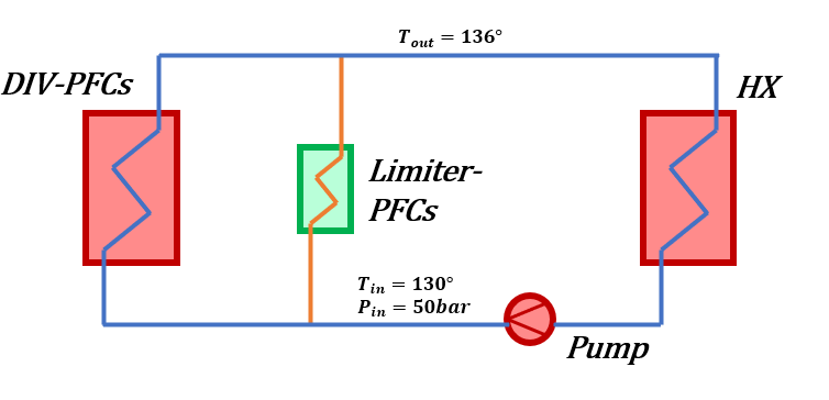
The identification of the possible configurations was followed by a preliminary study through Computational Fluid Dynamics of the thermo-hydraulic behaviour of the PFC cooling circuit. These innovative PFC layouts with tungsten lattices as sacrificial armor material were assumed as input for the analysis of the limiter PFC cooling water circuit in order to verify that the total pressure drop obtained was in line with the tolerable limits required for the potential integration of the limiter cooling circuits within the divertor PHTSs [6].
References
[1] F. Maviglia, R. Albanese, R. Ambrosino, W. Arter, C. Bachmann, T. Barrett, G. Federici, M. Firdaous, J. Gerardin, M. Kovari, et al., Wall protection strategies for DEMO plasma transients, Fusion Engineering and Design 136 (2018) 410–414[2] J. You, C. Bachmann, V. Belardi, M. Binder, D. Bowden, G. Calabro, P. Fanelli, M. Fursdon, I. Garkusha, S. Gerashchenko, et al., Limiters for demo wall protection: Initial design concepts & technology options, Fusion Engineering and Design 174 (2022) 112988[3] A. v. Müller, M. Binder, G. Calabro, R. De Luca, P. Fanelli, R. Neu, G. Schlick, F. Vivio, J.-H. You, Tailored tungsten lattice structures for plasma-facing components in magnetic confinement fusion devices, Materials Today 39 (2020) 146–147.[5] R. De Luca, P. Fanelli, S. Mingozzi, G. Calabro, F. Vivio, F. Maviglia, J. You, Parametric design study of a substrate material for a demo sacrificial limiter, Fusion Engineering and Design 158 (2020) 111721.[6] I. Moscato, IDM Report DIV-DEMO.S.1- T011-D002.

